
The coordinate model
A point inside the fundamental cell can be described as a combination of two basis vectors:
The values u and v express where the point lies relative to the cell. A point near the middle remains near the middle even when the cell changes from a rectangle to a rhombus.
TorusDraw stores this cell-relative information alongside the coordinates used for drawing on screen. That gives the application a stable mathematical representation and a convenient display representation.
The distinction matters whenever the cell changes. Instead of preserving obsolete screen positions, TorusDraw regenerates the visible geometry from the retained cell coordinates. The drawing therefore stretches and shears with the domain while keeping its topological placement.
The same representation supports repeated 2D copies, editing through any visible copy, project serialization, surface reshaping, boundary normalization and 3D placement.
Edge identifications
The base cell covers one unit in each cell-relative direction. Moving by a whole number enters a neighboring copy.
An orientation-preserving connection joins matching transverse positions directly. An orientation-reversing connection joins a transverse position to its reflection. In practical terms, a normal join wraps from one side to the other; a reversed join wraps and flips.
For repeated 2D rendering, the integer offset of a neighboring cell determines whether a reversed direction should be reflected. Odd offsets receive the flip; even offsets return to the original orientation.
| Edge configuration | Surface |
|---|---|
| No identified pairs | Plane |
| One preserved pair | Cylinder |
| One reversed pair | Möbius strip |
| Two preserved pairs | Torus |
| One reversed and one preserved pair | Klein bottle |
| Two reversed pairs | Projective plane |
The classification is not merely a label. It selects the boundary rules and the corresponding 3D map.
Repeated 2D rendering
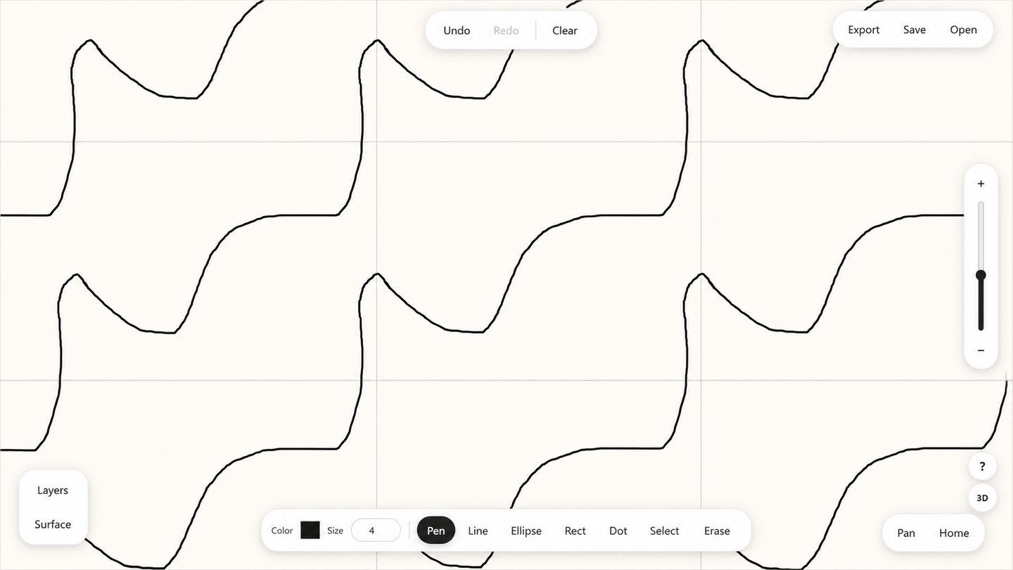
The workspace appears infinite, but the renderer does not create an unlimited grid.
It transforms the current viewport into cell coordinates, determines which integer-offset copies can intersect the visible area and renders only that finite set. A hard upper limit prevents highly skewed or tiny cells from producing uncontrolled work.
Each object exists once in the project state. The renderer applies the appropriate translation or reflection to draw it in each visible cell.
Hit testing follows the same logic. When a user selects an object through a repeated copy, the application records which copy was clicked but edits the original source object. A copy does not become a second object merely because it appears elsewhere on screen.
Seam-safe paths
A path that crosses a boundary is continuous on the quotient surface, but it may be discontinuous inside the rectangular parameter domain.
Mapping the complete path directly could produce a line through the interior of the 3D model. TorusDraw instead follows a deliberate sequence:
- Find where the path crosses integer cell boundaries.
- Split the path at those positions.
- Normalize each segment through the selected edge rule.
- Apply any required orientation reversal.
- Map the normalized pieces to the 3D surface.
Small numerical offsets keep exact boundary equality from being interpreted inconsistently. The result is a sequence of locally continuous surface pieces that meet at the intended quotient seam rather than forming a false chord.
Six surface maps
Plane
The direct affine image of the cell. Open dimensions remain visible boundaries.
Cylinder
The identified direction wraps around a circular axis. The open direction becomes height, while cell skew contributes to the angular phase.
Torus
Both identified directions become loops around a standard torus. The cell’s lengths, area and skew influence its dimensions and phase relationship. The seams agree, although a conventional 3D torus necessarily distorts the flat metric.
Möbius strip
The identified direction forms a loop with a half twist. One traversal returns to the same position with the transverse coordinate reversed.
Klein bottle
A classical self-intersecting immersion divided into formula regions. The self-intersection is part of visualizing the surface in ordinary 3D; it is not an additional quotient seam.
Projective plane
The square is transformed into a disk with antipodal boundary symmetry and then into a cross-cap immersion. Both reversed pairs meet according to the intended identification.
The custom WebGL pipeline
The 3D preview is implemented with custom WebGL rather than a general-purpose 3D framework.
- Classify the active surface.
- Create the quotient-domain transition rules.
- Create the topology-specific analytic map.
- Sample that map into a triangle mesh.
- Estimate normals through finite differences.
- Generate seam, boundary and grid geometry.
- Convert drawing content into ribbons or a texture.
- Upload buffers and textures.
- Render with camera, lighting, depth and transparency.
- Measure the seams and update the explanatory interface.
The meshes use different sampling densities according to the complexity of the surface. Camera controls use pointer orbit, perspective projection and constrained zoom, and the current WebGL view can be exported as a PNG.
Drawing on orientable and non-orientable surfaces
METHOD 01
Lifted ribbon geometry
Path-like objects can be sampled into thin ribbons that sit slightly above the surface. The offset prevents z-fighting and preserves a crisp vector-like appearance.
METHOD 02
Baked surface texture
Filled shapes and non-orientable surfaces are safer to render through a texture attached directly to the mesh.
A non-orientable surface has no globally consistent front side. A lifted path can therefore be displaced onto the wrong local side. Self-intersecting immersions add another risk: raised geometry may appear cut off or jump between nearby sheets.
Baking the paint into a cell texture avoids those assumptions. Edge and corner padding is generated with the same translated or reflected boundary rules so texture filtering does not reveal empty seams.
Editable vectors and destructive raster operations
TorusDraw preserves semantic objects for ordinary drawing and editing. A line remains a line. A rectangle remains transformable. Layers, widths, colors, groups and node editing remain available after creation.
Rub-erasing the interior of a filled vector shape is different. Maintaining a general vector-boolean subtraction system would add substantial complexity and could create unstable geometry.
For that operation, the application renders the filled shape into an offscreen pixel buffer, removes alpha beneath the eraser, crops the remaining image, detects disconnected opaque regions and stores the survivors as raster objects.
If the conversion or splitting fails, the source object is preserved rather than replaced with incomplete data. The project remains vector-based until the user performs an operation whose natural result is pixel-level destruction.
Project persistence
The project model is serializable as human-readable JSON. A .torusdraw file stores surface vectors, edge settings, objects, layers, colors, sizes, the cell-bound image, viewport state and preview settings.
Runtime-only resources such as decoded images and WebGL buffers remain outside the saved project.
Autosave writes the current project into IndexedDB after a short debounce. Startup recovery restores that record, while a full reset clears it. Compatibility logic supplies missing information for older projects, including coordinates, layers, preview settings and raster formats.
The product is intentionally local-first. Projects remain in the browser or in downloaded .torusdraw files, allowing them to be used and shared without an account, application server or cloud synchronization.
Performance safeguards
TorusDraw includes practical protections that keep demanding projects responsive:
- Visible repeated-cell copies are limited.
- Nearly degenerate cells are rejected.
- Extreme skew or aspect ratios trigger warnings.
- Dense grids reduce their drawing frequency.
- 2D redraws are grouped into animation frames.
- Browser pixel density is capped.
- 3D texture resolution is bounded.
- Mesh density is adapted to the surface type.
- Raster images and paint textures can be cached.
- Autosave is debounced and zoom ranges are constrained.
The most demanding workflows are large image projects, many objects across many visible cells, dense 3D meshes and filled-shape raster splitting. The safeguards focus on keeping these workloads controlled and predictable.
Testing and representation
The strongest automated tests focus on the property that is easiest to get visually close but mathematically wrong: seam agreement.
Representative points are sampled along identified boundaries for the cylinder, Möbius strip, torus, Klein bottle and projective plane. The mapped positions must agree within a strict numerical tolerance, including multiple twist settings for the more complex surfaces.
The preview repeats a version of this check at runtime and exposes a numerical seam error to the user. That value confirms that points declared equivalent by the quotient map meet in the selected parameterization. It does not prove that a surface is isometric or non-self-intersecting.
The interface identifies the standard torus’s metric distortion and presents the Klein bottle and projective plane as self-intersecting immersions. These are expected properties of representing the selected surfaces in ordinary 3D, while the seam measurements verify that identified boundaries still meet.
Architecture overview
The architecture is browser-native and local-first. The main complexity is not in external services; it is in keeping the geometry, editing model and two renderers consistent.
The same fundamental-cell representation supports drawing, repetition, seam handling, six 3D views, project continuity and responsive interaction. That coherence is what turns the project into one usable application.