Overview
TorusDraw is a custom browser application developed for the Department of Mathematics at Uppsala University. It brings object-based drawing, configurable surface geometry and real-time 3D visualization together in one focused workspace.
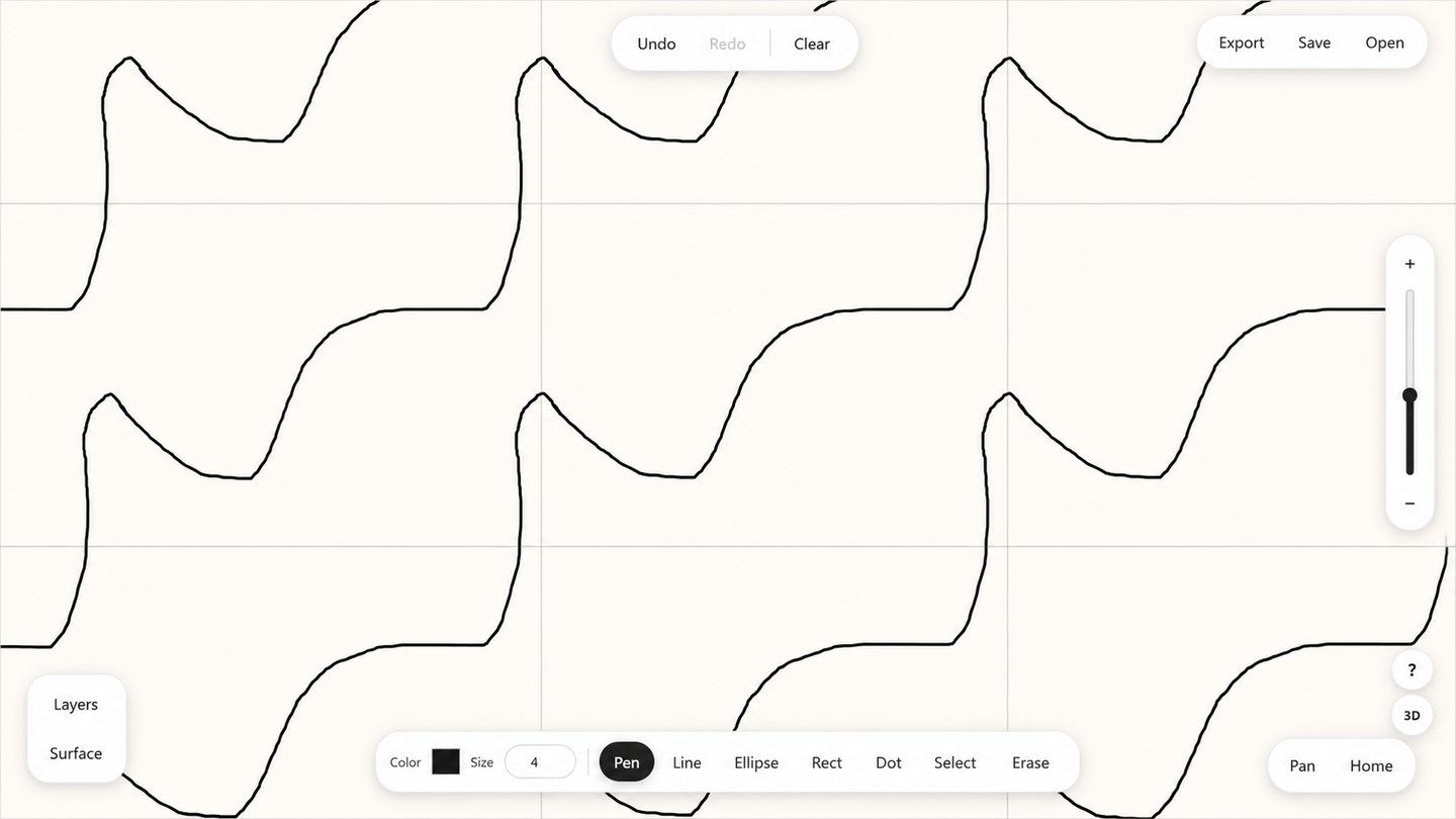
The application is built around a fundamental cell: a parallelogram defined by two basis vectors. Opposite edges can remain open, connect directly or connect with reversed orientation. Those choices determine whether the drawing behaves like a plane, cylinder, torus, Möbius strip, Klein bottle or projective plane.
Instead of treating the result as a repeated image, TorusDraw keeps the drawing structurally editable. Strokes and shapes remain objects. They can be selected, moved, resized, rotated, recolored, organized into layers and edited through any visible repeated copy. The same underlying coordinates also drive the 3D preview, so the 2D and 3D views are two representations of one project rather than separate illustrations.
The need
Topological surfaces are often introduced through diagrams of squares or polygons with arrows indicating how their edges should be identified. Those diagrams are mathematically useful, but they remain static. They do not let someone draw through a boundary, reshape the domain, edit the result or immediately inspect what the same construction means on a surface.
A normal drawing canvas could not solve that problem by itself. On an ordinary canvas, an edge is simply where the visible area ends. In TorusDraw, crossing an edge may mean reappearing on the opposite side. Depending on the chosen identification, the drawing may also need to reverse orientation.
The application therefore needed to support a familiar drawing workflow, mathematically meaningful edge behavior, editable objects, a reshapeable cell, live 3D representations, local recovery and practical desktop and touch use—all without splitting those requirements into unrelated tools.
The central challenge
Every point in the drawing had to remain understandable in several coordinate systems at once.
On screen, an object has an ordinary position. Relative to the fundamental cell, however, the same point is described by how far it lies along each of the two basis vectors. When the cell changes from a rectangle to a skewed parallelogram, the screen position changes, but its position within the cell should remain meaningful.
Edge crossings add another layer. A copy in a neighboring cell may be translated normally or reflected because of a reversed identification. A line that crosses a seam cannot be drawn directly through the interior of a 3D model; it must be divided at the boundary, normalized into the fundamental domain and continued from the corresponding identified point.
Some surfaces introduce unavoidable visual limitations as well. A Klein bottle and a projective plane cannot be embedded in ordinary three-dimensional space without self-intersection. A standard 3D torus also distorts the metric of a flat cell. The application needed to visualize these surfaces usefully without implying mathematical properties that the 3D representation cannot have.
The challenge was not to add a repeat effect. It was to create one coherent model in which drawing, editing, repetition, persistence and 3D visualization all agreed.
The approach
I designed the application around one principle: the fundamental cell and its cell-relative coordinates remain the source of truth.
Drawing points are stored relative to the two basis vectors. The visible 2D copies, boundary behavior, selection logic, project files and 3D placement are derived from that shared representation.
This separation keeps the interface approachable. Users work with familiar tools such as a pen, line, rectangle, ellipse, point marker, selection tool and eraser. Underneath those interactions, the application tracks the geometry required to preserve the surface behavior.
Editable project model
Objects, layers, images, cell vectors and surface settings remain structured data.
Quotient-domain rules
Edge connections determine how coordinates wrap, translate or reverse.
Repeated 2D workspace
The renderer creates only the visible cell copies while retaining one source object.
3D surface system
Topology-specific maps transform the same normalized coordinates into WebGL geometry and paint.
What I built
A topology-aware drawing workspace
The 2D workspace supports freehand drawing, lines, rectangles, ellipses and point markers. Lines can be constrained to regular angles, shapes can be drawn from their center and objects can be transformed after creation.
The selection system works across the repeated plane. A user can click an object in any visible repeated cell and still edit the one underlying source object. Objects can be moved, resized, rotated, flipped, duplicated, grouped, recolored and edited through nodes and Bézier handles where supported.
Configurable surfaces and edge identifications
The Surface panel lets users define the cell through two vectors and configure both pairs of opposite edges. Each pair can remain open, connect while preserving direction or connect while reversing direction.
From those rules, the application classifies and displays the relevant surface. When the cell changes, the drawing can remain attached to its cell-relative position, stretching or shearing with the new basis rather than remaining fixed to obsolete screen coordinates.
Layers and cell-bound images
Drawing layers can be created, reordered, hidden, deleted and given separate opacity. A background image can be attached to the cell, displayed with crop or stretch behavior and repeated with the same geometry as the drawing.
Real-time 3D exploration
The 3D preview supports orbiting, zoom, twist control, multiple display modes, surface grids, seam indicators, explanatory text, numerical seam-error reporting and PNG export.
Dedicated maps represent the plane, cylinder, torus, Möbius strip, Klein bottle and projective plane. The geometry responds to the cell’s dimensions, aspect and skew while preserving the intended boundary identifications.
Local project continuity
Projects can be saved as readable .torusdraw JSON files and reopened later. IndexedDB autosave provides recovery between sessions without requiring an account or application server. Separate PNG exports are available for the 2D drawing and current 3D view.
Desktop and touch interaction
Desktop use is supported through keyboard shortcuts and precise pointer tools. On compact screens, panels become bottom sheets, toolbars scroll horizontally, larger targets support coarse pointers, touch controls replace keyboard-only modifiers and two-finger gestures pan and zoom the 2D canvas.
Key engineering decisions
Store the drawing in cell-relative coordinates
Each point can retain coordinates relative to the cell basis. That allows the application to regenerate its visible position after the cell changes and keeps the drawing attached to the mathematical domain.
Treat edge identifications as executable geometry
A reversed connection changes repeated copies, seam crossing, path normalization, hit testing and 3D placement. The edge arrows describe active transformation rules rather than decorative metadata.
Split paths before mapping them to 3D
Boundary-crossing paths are divided into locally continuous pieces, normalized through the selected identification and only then placed on the surface. This avoids false chords through the interior of a model.
Use object geometry where possible and pixels where necessary
Ordinary drawing remains structured and editable. A specifically destructive fill erase becomes raster content when pixel-level alpha removal is the more reliable representation.
Combine lifted paths with baked surface textures
Suitable outlines become thin ribbons above the mesh. Filled content and paint on non-orientable or self-intersecting surfaces are baked into textures to avoid incorrect local-side assumptions and clipping artifacts.
Explain how each 3D representation behaves
The preview reports sampled seam error and identifies when a model introduces metric distortion or an expected self-intersection, helping users interpret each surface correctly.
Testing and reliability
Automated tests cover the most important mathematical invariant: identified boundary points must meet on the generated surface.
The topology tests cover the cylinder, Möbius strip, torus, Klein bottle and projective plane. Representative maps and multiple twist values are checked, and paired seam positions must agree within a strict numerical tolerance.
Additional smoke tests protect deep cloning of representative project data and important responsive-layout rules. The application also includes defensive behavior inside normal workflows:
- Near-collapsed cells are rejected before replacing the current geometry.
- Extreme aspect ratios or skew produce warnings and safer rendering.
- Visible repeated copies are capped to prevent uncontrolled work.
- Reshaping a populated cell requires explicit confirmation.
- Failed destructive raster processing preserves the original object.
- WebGL failure produces a readable message rather than an empty panel.
- Project parsing and browser-storage failures are caught.
- At least one drawing layer is maintained.
Automated coverage is intentionally strongest around seam correctness, supported by runtime safeguards for geometry, persistence, rendering and destructive editing. Broader interaction, device, accessibility and high-load scenarios remain valuable areas for continued test expansion.
The result
TorusDraw turns a static mathematical diagram into an editable instrument.
A user can create one drawing, watch it repeat across a skewed lattice, change how the boundaries are connected, reshape the cell and immediately inspect the result on a corresponding 3D surface. The underlying work remains editable rather than being flattened into a single image.
The finished application combines object-based drawing, six quotient-surface classes, orientation-preserving and orientation-reversing edge behavior, layers and images, project files, autosave recovery, 2D and 3D export, responsive interaction and topology-focused diagnostics.
The value of the result is not that it removes the complexity of the mathematics. It gives that complexity a direct, manipulable interface.
My role and responsibility
I was responsible for turning the mathematical requirements into a coherent browser product.
That work included shaping the interaction model, designing the drawing and surface controls, implementing the object-based Canvas workspace, building the basis-coordinate and edge-identification logic, connecting the 2D project model to six 3D surface maps, developing the custom WebGL preview and implementing layers, persistence, export and autosave.
I also adapted the interface for keyboard, pointer and touch use and added mathematical tests, runtime diagnostics and failure safeguards.
The project required product design, geometry, real-time graphics, state management, responsive interaction and technical communication to work as one system rather than as separate demonstrations.
Technical highlights
Cell-relative geometry
Objects retain coordinates relative to the two basis vectors, allowing the cell to change shape without severing the drawing from its mathematical position.
Executable edge identifications
Open, preserved and reversed pairs affect repeated copies, seam transitions, hit testing, classification and 3D placement.
Seam-safe surface mapping
Paths are divided and normalized at cell boundaries before being mapped onto topology-specific WebGL meshes.
Editable object model
Strokes and shapes remain structured for selection, transformation, grouping, layers and project reopening.
Local-first persistence
Readable project files and debounced IndexedDB recovery provide continuity without accounts or cloud storage.
Interpretable 3D visualization
Numerical seam diagnostics are paired with concise explanations of metric distortion and expected self-intersection.
Scope and representation
TorusDraw is deliberately focused on editable drawings across identified surfaces. The following boundaries clarify how its tools and visualizations are intended to be used.
- The 3D views prioritize correct seam relationships; a curved model cannot preserve every distance from the flat cell.
- The Klein bottle and projective plane use standard self-intersecting immersions because these surfaces cannot be displayed in ordinary 3D without passing through themselves.
- The Hom tool focuses on practical basis displacement and cell-crossing information rather than computing a complete homology group.
- Rub-erasing inside a filled vector shape converts the affected result to raster content so the destructive edit remains predictable.
- The visual Canvas workspace does not yet provide every editing operation through a structured screen-reader interface.
- Projects are local-first by design: files and browser recovery work without accounts, cloud collaboration or server-side storage.
- Large images and complex projects are managed through rendering safeguards rather than fixed project-size limits.
- Automated tests concentrate on mathematical seam correctness, with broader interaction coverage remaining an area for expansion.